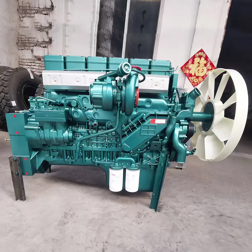
In modern electronic common-rail commercial diesel engines (Sinotruk Howo D12, Weichai WP10/WP12, Shacman X3000, Foton Cummins ISG), the crankshaft speed sensor and camshaft position sensor provide the vital dual-heartbeat synchronization signals required by the engine ECU to determine top dead center (TDC) and calculate fuel injection timing. Operating under severe engine bay heat (up to 120°C) and flywheel oil-mist contamination across African and Latin American haulage routes, diagnosing sensor air gap deviations (0.5mm to 1.5mm), harness shielding damage, and metallic debris accumulation prevents prolonged engine cranking, cylinder misfiring, and sudden highway stalling.
1. Technical Specification Comparison: Crankshaft vs. Camshaft Position Sensors
Signal generation physics, sensor target tooth wheels, and ECU failure fallback strategies:
| Engineering Parameter | Crankshaft Engine Speed Sensor (Primary Signal) | Camshaft Phase / Position Sensor (Secondary Signal) |
|---|---|---|
| Sensor Technology | Variable Reluctance (Inductive magnetic pickup coil) | Hall Effect digital sensor (Active semiconductor IC chip) |
| Target Wheel Location | Flywheel ring gear or front crankshaft damper pulley (58+2 teeth) | High-pressure fuel pump drive gear or camshaft gear (7+1 tooth pattern) |
| Output Signal Waveform | Alternating Current (AC) analog sine wave (Voltage rises with engine RPM) | Direct Current (DC) 0V – 5V square-wave digital pulse signal |
| Primary ECU Function | Measures engine RPM and precise crankshaft angular velocity | Identifies Cylinder #1 compression stroke vs. exhaust stroke (Phase recognition) |
| Operating Air Gap Clearance | Strictly 0.5 mm – 1.2 mm between sensor pole pin and target tooth | 0.8 mm – 1.5 mm sensor-to-gear tooth clearance |
| Resistance Specification | approx. 800 – 1,200 Ohms across terminal pins @ 20°C | Active Hall IC: Not tested with simple ohmmeter (Requires 5V/24V power supply) |
| Wiring Harness Shielding | Braided metal mesh ground shield (Protects signal against starter alternator noise) | 3-Wire shielded cable (Power 5V, Signal Ground, Digital Output) |
| ECU Fallback Mode If Failed | Engine cuts out immediately (No engine speed = injection shutoff) | Extended cranking (3 to 5 sec delay); ECU guesses stroke from flywheel signal |
2. The Dual-Signal Synchronization Process: Determining Injection Timing
A four-stroke diesel engine requires two complete crankshaft rotations (720 degrees) for one engine cycle:
- The Crankshaft 58+2 Missing Tooth Gap: The flywheel target wheel features 58 evenly spaced teeth and a two-tooth missing gap. When this gap sweeps past the magnetic sensor pole, the AC sine wave collapses, signaling to the ECU that Cylinder #1 and #6 are approaching Top Dead Center (TDC). However, the crankshaft alone cannot determine whether Cylinder #1 is on compression or exhaust.
- The Camshaft Synchronization Stamp: The camshaft rotates at half crankshaft speed (one rotation per 720 degrees). The unevenly spaced tooth on the camshaft gear triggers a single digital pulse, confirming to the ECU that Cylinder #1 is on its compression stroke, triggering common-rail pilot and main fuel injection pulses.

3. Troubleshooting Common Sensor Malfunctions in Field Operations
Field mechanics can identify failing position sensors through diagnostic trouble codes and starting behavior:
| Observed Engine Symptom | Most Probable Root Cause | Immediate Corrective Action |
|---|---|---|
| Engine cranks 5 to 8 seconds before starting, runs normally once started | Camshaft sensor failed or harness open-circuit; ECU takes multiple flywheel turns to guess cylinder phase | Scan ECU for fault code P0340/P0341; test camshaft sensor 5V power supply; replace camshaft sensor |
| Engine cuts out instantly while driving hot; restarts after cooling down | Internal copper winding wire inside the crankshaft sensor expands and breaks when hot, reconnecting when cool | Pour water over sensor body to test thermal recovery; test internal resistance hot (>2,000 Ohms = bad); replace sensor |
| Engine misfires violently and smokes under load above 1,500 rpm | Excessive air gap (>1.8mm) or metal filings stuck to magnetic sensor tip, weakening AC voltage signal | Unscrew sensor; wipe iron filings off magnetic tip; adjust air gap with copper shims to exact 0.8mm |
| Engine cranks vigorously with starter motor but will not fire at all | Total failure of crankshaft sensor (No RPM signal detected by ECU; tachometer needle stays dead at zero) | Watch tachometer while cranking: if needle remains completely dead, replace crankshaft speed sensor |
4. Step-by-Step Air Gap Calibration Protocol
Setting sensor air gap incorrectly causes signal dropouts or destroys the sensor tip against the flywheel:
- Inspect the Target Tooth Face: Rotate the engine by hand using a flywheel barring tool. Inspect the target teeth through the sensor mounting hole for physical damage, broken teeth, or excessive runout.
- Measure Sensor Depth with a Depth Micrometer: Measure the distance from the aluminum flywheel bellhousing mounting face to the crest of a target tooth. Measure the length of the sensor body from its mounting collar to the pole tip.
- Calculate Shimming Thickness: Subtract the sensor length from the housing depth. Add or remove copper sealing washers beneath the sensor flange until the clearance equals 0.8 mm to 1.0 mm.
- Torque the Mounting Bolt: Tighten the M6 retaining bolt to 8 – 10 N·m. Rotate the flywheel 360 degrees by hand to verify zero mechanical contact between the sensor tip and the target wheel.
Frequently Asked Questions
Q: What causes metallic debris to stick to the crankshaft sensor tip?
A: The crankshaft sensor contains a permanent magnet. Normal friction wear from the engine starter bendix gear or flywheel clutch teeth generates microscopic steel dust that accumulates on the magnetic tip, distorting signal voltage.
Q: Can a 2-wire inductive sensor be replaced with a 3-wire Hall-effect sensor?
A: No. The internal electrical circuitry and ECU processing algorithms are completely incompatible. Inductive sensors generate self-induced analog AC voltages, while Hall sensors require external 5V/12V DC power to switch digital ground gates.
Q: Where can fleet operators source genuine Bosch and Weichai engine position sensors?
A: Browse our complete electrical sensor inventory in the Heavy-Duty Spare Parts Category, inspect original Diesel Engine Assemblies, or consult our International FAQ Center.
Request Engine Sensor Quotation & Electronic Parts Catalog
Recommended Semi-Trailers
 Howo 8x4 Dump Truck |  BYD Sealion 06 EV |  Geely EX5 |