On modern commercial heavy tractor heads and high-speed logistics semi-trailers (Sinotruk Howo T7/MAX, Shacman X3000, BPW/SAF disc axles), the pneumatic floating air disc brake caliper (Knorr-Bremse SN7/SB7, WABCO PAN22 series) delivers superior high-speed fade resistance and 20% shorter stopping distances compared to traditional S-cam drum brakes. Operating under severe thermal dissipation cycles (rotor disc temperatures exceeding 600°C), verifying internal automatic running clearance adjuster operation (0.6mm to 1.2mm pad gap), replacing torn guide pin rubber bellow boots, and evaluating disc rotor surface heat-checking cracks prevents dragging calipers, uneven pad taper wear, and fatal highway brake loss.
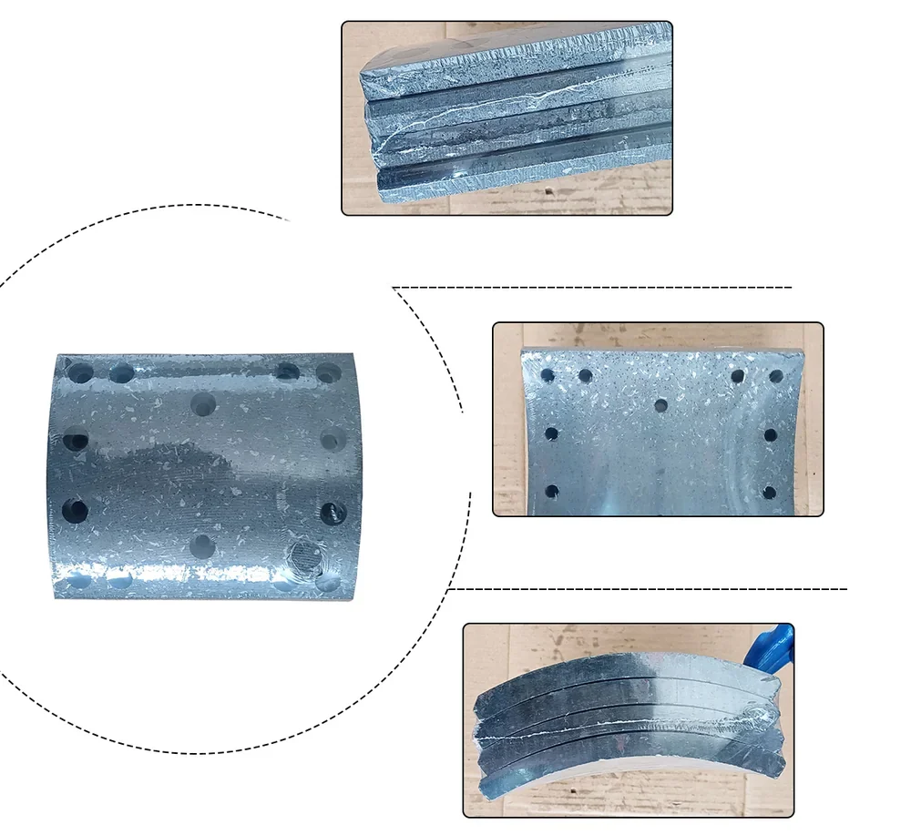
1. Technical Specification Comparison: Pneumatic Drum Brake vs. Air Disc Brake (ADB)
Braking response times, running clearances, heat fade thresholds, and maintenance weights across heavy vehicle foundation brakes:
| Engineering Parameter | Conventional S-Cam Pneumatic Drum Brake (420x180mm) | Pneumatic Floating Air Disc Brake (Knorr SN7 / 22.5" Wheel) |
|---|---|---|
| Braking Actuation Mechanism | Rotary S-camshaft expanding two curved brake shoes outward | Pneumatic lever mechanism pushing twin synchronized thrust tappets |
| Running Clearance Adjustment | External manual or automatic slack adjuster on camshaft spline | Integrated internal one-way clutch automatic clearance adjuster |
| Nominal Running Pad / Shoe Clearance | Wide clearance: approx. 1.5 mm – 2.5 mm shoe-to-drum gap | Tight running gap: strictly 0.6 mm – 1.2 mm total pad clearance |
| Braking Response Latency | approx. 0.35 to 0.50 seconds pneumatic line delay | Rapid bite: approx. 0.15 to 0.25 seconds (Shorter stopping distance) |
| Brake Fade Resistance Threshold | Fades severely at temperatures >350°C (Drum expands away from shoes) | Stable up to 600°C – 700°C (Rotor expands into caliper pads) |
| Brake Rotor / Drum Metallurgy | Cast iron brake drum (Weight: approx. 45 – 55 kg) | Internally ventilated cast iron rotor disc (Weight: 32 – 38 kg) |
| Guide Pin Mounting Architecture | Rigid spider bracket mounting | Floating caliper sliding on dual sealed guide pins (Fixed + Floating pin) |
| Friction Lining Wear Life | approx. 60,000 – 80,000 km | approx. 100,000 – 140,000 km (Visual pad wear indicator pins) |
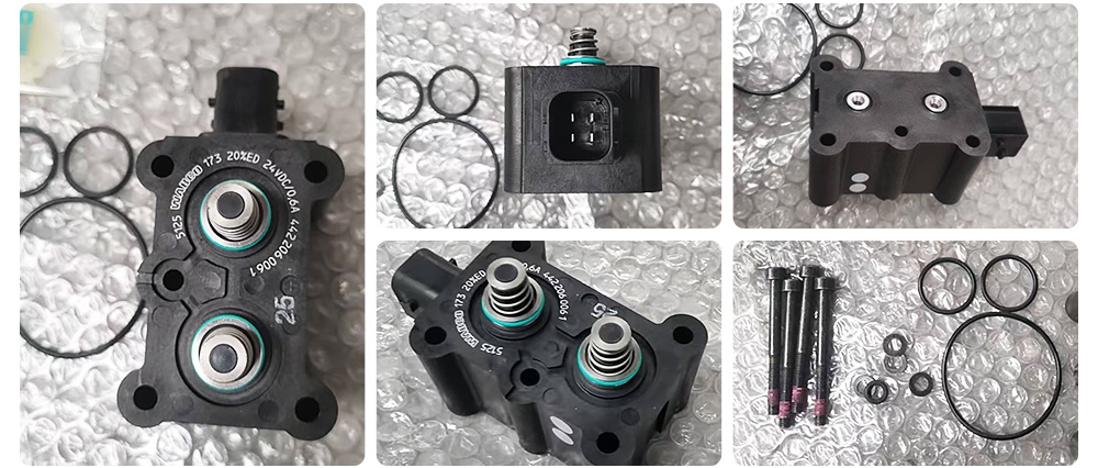
2. Kinematics of the Floating Caliper: Dual Thrust Tappet Synchronous Adjustment
An Air Disc Brake caliper does not clamp pads through direct hydraulic fluid pressure:
- The Rotary Lever Mechanism: Compressed air from the Type 20/24 service brake chamber pushes a push-rod against the internal eccentric rotary lever. The lever pivots across needle bearings, converting horizontal air chamber thrust into tens of thousands of kilograms of forward clamping force.
- Synchronized Twin Threaded Tappets: The rotary lever pushes a heavy bridge plate housing two synchronized, gear-coupled threaded thrust tappets. These tappets advance forward simultaneously, pressing the inner brake pad against the ventilated rotor disc.
- The Floating Caliper Reaction: As the inner pad contacts the rotor, the reactionary clamping force pulls the entire floating caliper sliding body backward along its sealed guide pins, drawing the outer brake pad into equal clamping pressure against the outside rotor face.
- The One-Way Clutch Auto-Adjuster: Inside the bridge, a spring-loaded one-way wrap clutch monitors lever stroke. As friction pads wear down, the adjuster automatically rotates the threaded tappets forward during each brake release, maintaining a constant 0.8mm to 1.0mm running gap over the entire life of the pad.
3. Troubleshooting Caliper Dragging & Rotor Heat Checking Cracks
Smoking wheel ends, dragging brakes, and deep rotor cracks indicate critical caliper failures:
| Observed Brake Malfunction | Most Probable Root Cause | Immediate Corrective Action |
|---|---|---|
| Wheel end smoking hot (>200°C) after highway travel; pads worn to metal | Caliper seized on guide pins due to torn rubber bellow boots and road salt corrosion | Remove caliper; polish guide pins or install new pin/boot kit; replace glazed pads |
| Uneven brake pad taper wear (Inner pad 20mm thick, outer pad 5mm thick) | Floating caliper sliding mechanism binding; guide pin brass sleeve corroded solid | Inspect guide pin sliding resistance (Must slide smoothly by hand); replace guide sleeve kit |
| Excessive brake pedal travel; brakes feel soft and delayed | Internal automatic clearance adjuster one-way clutch slipping; tappets fail to advance | Perform manual adjuster check with 10mm wrench; replace internal adjuster drive assembly |
| Surface hairline spider-web cracks covering the rotor braking face | Normal thermal expansion stress relief ("Heat Checking"); acceptable if under 0.5mm depth | Acceptable if cracks do not extend to outer rotor rim or exceed 75% of pad contact width |
4. Step-by-Step Auto-Adjuster Functionality & Guide Pin Inspection Protocol
Verifying internal adjuster operation during routine fleet pad replacement:
- Remove the Rubber Inspection Cap: Locate the shear-point drive adapter on the rear caliper body. Pry off the black protective rubber weather cap.
- Reset the Tappets Manually: Place a 10mm ring wrench on the hex drive adapter. Turn counter-clockwise to retract the twin threaded tappets back into the caliper housing to allow installation of fresh 30mm-thick brake pads. (A healthy adjuster produces a distinct rhythmic clicking sound).
- Pump Service Brakes 5 Times: Start the engine and charge air tanks to 0.8 MPa. Have an assistant depress the foot brake pedal firmly five times.
- Observe Automated Adapter Rotation: Watch the 10mm hex adapter. On each brake stroke release, the hex adapter must visibly rotate clockwise in incremental micro-steps! This confirms the internal one-way clutch is functioning and advancing the tappets forward automatically.
- Verify Floating Caliper Slide Movement: With pads removed, push and pull the caliper body horizontally along its guide pins by hand. The caliper must slide freely over its 25mm to 30mm guide stroke with zero mechanical binding.
Frequently Asked Questions
Q: When must a cracked brake disc rotor be condemned and replaced immediately?
A: Surface hairline cracks (under 1.0mm depth) are normal. However, if any single crack extends completely through to the outer or inner circular edge of the rotor, or if a crack bridges completely through the ventilated cooling vanes, the rotor must be condemned and replaced immediately to prevent explosive rotor shattering.
Q: What happens if an untrained mechanic uses an air impact wrench to retract the caliper tappets?
A: Using an impact wrench will instantly strip the internal shear adapter or shatter the one-way clutch drive gear teeth! Tappets must strictly be retracted manually using a hand wrench with moderate torque under 25 N·m.
Q: Where can fleet operators source genuine Knorr-Bremse, WABCO, and Meritor air disc brake calipers and pad kits?
A: Browse our complete foundation brake inventory in the Heavy-Duty Spare Parts Category, inspect original Commercial Heavy Trucks, or consult our International FAQ Center.
Request Air Disc Brake Calipers & Rotor Replacement Quotation
Recommended Semi-Trailers
 3 Axle Flatbed Trailer | 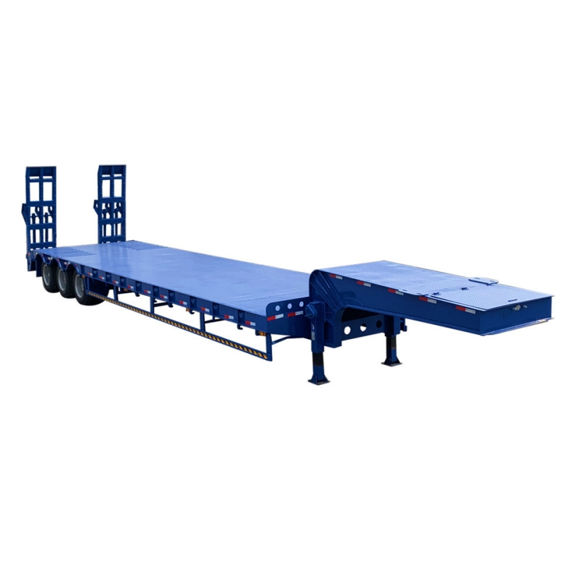 3 Axle Lowboy Trailer |  3 Axle Container Chassis Trailer |