In deep foundation bored piling for bridges, skyscrapers, and mining infrastructure across Africa and Southeast Asia (SANY SR285/SR360, XCMG XR280/XR360, Bauer BG series), the telescopic Kelly bar (interlocking mechanical lock or friction drive) transmits up to 280 to 360 kN·m of rotary torque and 200 kN of downward crowd force to the drilling auger at depths up to 80 meters. Operating in hard granite bedrock and abrasive laterite boulders, diagnosing drive key (spline strip) wear, repairing stripped locking pockets via hardfacing, and preventing telescopic section sticking eliminates catastrophic in-hole stuck drill pipe disasters.
1. Technical Specification Comparison: Interlocking (Mechanical Lock) vs. Friction Kelly Bars
Torque capacities, crowd force transmission, drilling depths, and geological suitability across Kelly bar types:
| Engineering Parameter | Friction Type Telescopic Kelly Bar | Interlocking (Mechanical Lock) Kelly Bar (Mining & Rock Spec) |
|---|---|---|
| Torque & Crowd Transmission Mode | Frictional contact between external drive keys under downward thrust | Positive mechanical lock engagement via internal drive keys and milled locking pockets |
| Maximum Downward Crowd Force | Limited (approx. 60 – 100 kN effective crowd before slipping) | Full crowd thrust transmission (200 – 300 kN hydraulic pull-down force) |
| Telescopic Section Count | 4, 5, or 6-section ultra-deep slim telescopic tubes | 3, 4, or 5-section heavy-wall alloy steel tubular sections |
| Drilling Depth Range | Deep piles: 60m up to 110+ Meters in soft alluvial soils | Standard heavy piles: 40m to 85 Meters maximum depth |
| Optimal Geological Formations | Soft clay, silt, river sand, gravel beds, non-cohesive soils | Hard weathered granite, limestone bedrock, basalt, bauxite rock |
| Raw Tube Metallurgy | 27SiMn or 35CrMo Seamless Alloy Steel Tubing (Heat-treated) | High-tensile 35CrMo / 42CrMo seamless forged alloy steel tubes |
| Drive Key Hardness & Wear Layer | High-frequency induction-hardened steel keys (50 – 55 HRC) | Quenched alloy steel keys + submerged arc hardfacing (58 – 62 HRC) |
| Operator Operating Complexity | Simple: Continuous vertical feed without rotational indexing | Advanced: Requires precise rotational indexing to lock and unlock lugs |

2. Kinematics of the Interlocking Mechanism: How Mechanical Locking Delivers 300 kN of Crowd
Hard rock drilling requires driving the auger teeth into bedrock using the rig's full weight:
- The Stepped Locking Pocket Architecture: On an interlocking Kelly bar, each inner telescopic tube features precision-milled locking pockets (teeth) spaced at 2 to 3-meter vertical intervals along its longitudinal drive keys.
- The Locking Sequence: The operator lowers the drill string to the desired depth, then gently rotates the rotary drive table clockwise by 15 to 30 degrees. The drive keys on the outer tube slide into the recessed locking pockets of the inner tube.
- Transferring 300 kN Crowd Force: Once locked, the rig's hydraulic crowd cylinder pushes downward against the outer bar. This vertical force transfers directly through the locked teeth to the cutting tool without slipping, forcing tungsten-carbide bullet teeth into solid 80 MPa granite.
- The Unlocking Sequence: Before hoisting the full bucket to surface, the operator rotates the rotary table counter-clockwise by 30 degrees to disengage the keys from the pockets, followed by smooth vertical cable extraction.
3. Troubleshooting Kelly Bar Slippage & Jamming in Deep Boreholes
Failure to lock under crowd or refusal of telescopic sections to retract indicates critical mechanical wear:
| Observed Kelly Bar Malfunction | Most Probable Root Cause | Immediate Corrective Action |
|---|---|---|
| Drill rig applies downward crowd, but Kelly bar slips through without locking | Rounded or chipped locking pocket corners; drive keys worn past 6mm limit; operator missing rotation angle | Inspect drive keys and locking pockets with inspection mirror; hardface worn corners; verify indexing |
| Telescopic bar jams inside borehole; hoist winch cannot pull bar up | Sand slurry packed tightly between telescopic tubes; bent tube caused by excessive lateral crowd flex | Tap rotary drive gently while hoisting; flush borehole with high-pressure bentonite mud to loosen sand |
| Severe violent banging and clattering during rotary drilling | Excessive clearance between rotary drive sleeve keys and Kelly bar outer drive keys (>10mm wear gap) | Measure drive key thickness with calipers; build up drive keys with wear-resistant welding rods |
| Bottom terminal spring pack crushed flat or broken | Operator slamming Kelly bar into bottom stop during rapid gravity lowering | Replace internal heavy helical damping spring pack and polyurethane shock buffer pads |
4. Step-by-Step Drive Key Hardfacing & Rebuilding Protocol
Restoring worn drive keys back to factory profile extends Kelly bar service life by 2,000 hours:
- Extract the Telescopic Sections: Disassemble the Kelly bar on flat horizontal support horses. Clean all grease and abrasive slurry off the tubes using high-pressure steam washers.
- Measure Key Wear with a Contour Gauge: Measure the width and height of the longitudinal drive keys. If side wear exceeds 4.0 mm or locking pocket faces are chamfered by more than 5.0 mm, rebuilding is mandatory.
- Pre-Heat the 35CrMo Alloy Tube: Pre-heat the tube section locally to 150°C to 180°C using propane heating torches to prevent hydrogen-induced underbead cracking in the alloy base metal.
- Apply Buffer Pass (E7018 / ER50-6): Lay down an initial ductile transition layer using low-hydrogen steel wire to ensure strong metallurgical bonding to the high-tensile tube.
- Apply High-Chromium Hardfacing Cap: Weld two passes of high-chromium carbide hardfacing wire (e.g., FeCr-C alloy wire delivering 58 to 62 HRC hardness). Grind the welded profile flat to a clean 90-degree square shoulder using a template guide.
Frequently Asked Questions
Q: Why should grease NEVER be applied to the exterior of Kelly bar tubes?
A: Applying grease to the outside of telescopic Kelly tubes attracts abrasive silica sand and pulverized rock dust, creating a grinding paste that cuts through steel drive keys in under 100 operating hours. Kelly bars must operate completely dry!
Q: What causes an interlocking Kelly bar tube to split longitudinally?
A: Longitudinal tube splitting occurs when the operator rotates the drill string at full torque while the keys are only half-way engaged in a locking pocket, focusing hundreds of tons of torsional force onto a tiny 20mm point on the tube wall.
Q: Where can piling contractors procure genuine Kelly bars, drive keys, and drilling tools?
A: Browse our complete foundation engineering catalog in the Construction Machinery Category, view original Heavy-Duty Spare Parts, or consult our International FAQ Center.
Request Kelly Bar Engineering Drawings & Factory Quotation
Recommended Semi-Trailers
 3 Axle Flatbed Trailer | 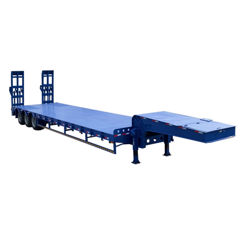 3 Axle Lowboy Trailer |  3 Axle Container Chassis Trailer |