In ultra-heavy commercial mining tippers and 100-ton abnormal heavy-haul prime movers (Weichai WP13G 550HP-580HP, Sinotruk MC13 540HP), the regulated two-stage sequential turbocharging system (series-connected high-pressure small turbo and low-pressure large turbo) delivers massive low-end torque (2,500 N·m at just 1,000 rpm) and high-altitude Andean breathing performance. Diagnosing pneumatic wastegate bypass flap sticking, testing interstage intercooler pressure drops (exceeding 0.03 MPa), and verifying 3.2-bar absolute boost pressures prevents severe turbo lag, high exhaust gas temperatures (EGT > 720°C), and high-RPM power choking.
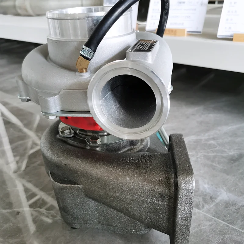
1. Technical Specification Comparison: Single Turbocharger vs. Regulated Two-Stage Turbocharging
Boost pressure levels, impeller sizes, exhaust gas bypass mechanisms, and operational altitudes across heavy diesel engines:
| Engineering Parameter | Standard Single Wastegate Turbocharger (e.g., WP12 430HP) | Regulated Two-Stage Sequential Turbo System (e.g., WP13 580HP) |
|---|---|---|
| Turbocharger Arrangement | Single fixed or wastegate turbo mounted on exhaust manifold | Two turbos in series: High-Pressure (HP Small) + Low-Pressure (LP Large) |
| Maximum Absolute Boost Pressure | approx. 2.2 – 2.6 bar (approx. 32 – 38 psi gauge) | Ultra-high boost: approx. 3.2 – 3.8 bar (approx. 46 – 55 psi gauge) |
| Low-End Torque Delivery @ 1,000 RPM | approx. 1,600 – 1,800 N·m (Subject to standard turbo spool lag) | Full 2,400 – 2,600 N·m (Small HP turbo spools instantly in 1.2 sec) |
| Interstage Charge-Air Intercooling | None (Single post-compressor air-to-air charge cooler) | Dual-stage cooling: Interstage cooler between turbos + Main intercooler |
| Exhaust Gas Bypass Control Valve | Single pneumatic actuator venting into downpipe | Dual control: Modulated HP turbine bypass valve + LP wastegate flap |
| Compressor Pressure Ratio Per Stage | Single stage must achieve total pressure ratio $\Pi \approx 2.8$ | Shared compression: Stage 1 ($\Pi_1 \approx 1.8$) x Stage 2 ($\Pi_2 \approx 2.0$) |
| High-Altitude De-Rating Threshold | Loses approx. 18% power at 3,000m Andean mining altitude | Zero power loss up to 4,500m (Maintains sea-level oxygen mass flow) |
| Optimal Commercial Application | Standard highway 6x4 tractors, 45,000L fuel tankers | 8x4 65-ton mining dumpers, heavy ballast tractors, 100T lowboys |

2. Kinematics of Sequential Two-Stage Compression: Low-End Spool to High-RPM Bypass
Two-stage turbocharging splits airflow and exhaust enthalpy across two distinct operational regimes:
- Low-RPM High-Torque Phase (800 to 1,300 RPM): At low engine speeds, exhaust flow is weak. The high-pressure turbine bypass valve remains closed. 100% of exhaust gas streams through the small HP turbine, spooling it rapidly to 130,000 rpm. Simultaneously, the small HP compressor compounds air pre-compressed by the large LP turbo, delivering 2.5 bar boost almost off-idle.
- High-RPM Transition Phase (1,400 to 2,100 RPM): As exhaust volume surges under full engine power, the small HP turbine would become a massive bottleneck, causing severe exhaust backpressure. The ECU modulates the pneumatic bypass actuator, cracking open the HP turbine bypass valve.
- The LP Main Workhorse Takeover: Exhaust gas bypasses the small turbine, streaming directly into the massive low-pressure (LP) turbine wheel. The large LP compressor takes over the bulk of airflow compression, delivering over 45 cubic meters of chilled air per minute without choking engine breathing.

3. Troubleshooting Bypass Flap Sticking & Interstage Pressure Drops
Loss of low-end grunt or sudden loss of top-end highway power indicates bypass valve failure:
| Observed Engine Symptom | Most Probable Root Cause | Immediate Corrective Action |
|---|---|---|
| Engine has zero low-end pulling power; black smoke until 1,500 RPM | HP turbine bypass valve stuck open (Carbonized soot on pivot bushing); exhaust gas bypassing small turbo | Free bypass linkage manually; lubricate pivot shaft with graphite spray; replace pneumatic actuator |
| Engine pulls hard at low RPM, but chokes, knocks, and overheats above 1,600 RPM | HP turbine bypass valve stuck closed; small turbine choking exhaust flow; EGT exceeds 750°C | Inspect 24V PWM solenoid valve; test pneumatic supply line pressure; replace seized bypass flap assembly |
| High-pitched screaming whistle under full throttle; boost pressure drops 0.5 bar | Interstage aluminum connector pipe split or silicone coupler blown off between HP and LP compressors | Pressure-test interstage charge piping at 0.35 MPa; replace torn 4-ply aramid silicone hose clamps |
| High oil consumption; oil pooling between the two turbo compressor housings | Low-pressure turbo oil drain pipe caked with carbon sludge, forcing oil past turbine dynamic piston rings | Remove and clean low-pressure turbo oil drain tube; verify crankcase breather pressure is under 0.05 bar |
4. Step-by-Step Pneumatic Bypass Valve Calibration & Leak Testing Protocol
Testing two-stage bypass actuator stroke using a regulated hand pressure pump:
- Isolate the Pneumatic Actuator: Disconnect the nylon signal air line leading from the 24V PWM solenoid valve to the high-pressure turbine bypass actuator canister.
- Connect Pressure Hand-Pump with Gauge: Connect a manual pneumatic calibration pump equipped with a precision 0 to 0.4 MPa test gauge.
- Measure Cracking Pressure & Full-Stroke Travel: Slowly pump air pressure into the actuator while observing the mechanical linkage connecting to the turbine internal flap:
- Initial Cracking Pressure: The linkage rod must begin moving at exactly 0.12 MPa to 0.14 MPa (1.2 to 1.4 bar).
- Full Open Stroke (12mm Travel): The rod must travel smoothly without binding to its mechanical stop at 0.24 MPa (2.4 bar).
- If Linkage Binds or Stutters: The high-temperature Inconel internal wastegate flap pivot pin is galled inside its cast-iron turbine housing bushing. Tap lightly with a brass drift and lubricate with high-temperature molybdenum disulfide dry film.
- Perform 60-Second Diaphragm Leak-Down Test: Pump actuator to 0.25 MPa and hold. The pressure gauge needle must remain completely static for 60 seconds. A drop of > 0.02 MPa indicates a perforated internal rubber diaphragm, requiring actuator replacement.
Frequently Asked Questions
Q: Why is two-stage turbocharging essential for mining trucks operating in the South American Andes (Peru / Chile)?
A: At 4,500 meters altitude, atmospheric air density drops by nearly 40%. A single turbocharger cannot spin fast enough to compress sufficient oxygen without over-speeding and exploding. Two-stage series turbocharging splits compression ratios, supplying sea-level air mass flow to maintain full 550HP without smoke.
Q: What causes two-stage turbo interstage intercoolers to clog internally?
A: Microscopic blow-by oil mist from the engine compressor mixed with soot coats the internal aluminum tubes of the interstage charge cooler, acting like a thermal blanket that spikes intake air temperature by 40°C.
Q: Where can mining and transport fleets procure genuine Weichai and Sinotruk two-stage turbochargers?
A: Browse our complete induction system inventory in the Heavy-Duty Spare Parts Category, inspect original Commercial Heavy Trucks, or consult our International FAQ Center.
Request Two-Stage Turbochargers & Powertrain Quotation
Recommended Semi-Trailers
 Sinotruk Howo Tractor Head |  Shacman F3000 Tractor Truck |  Howo TX 430hp 6x4 Tractor Truck |